
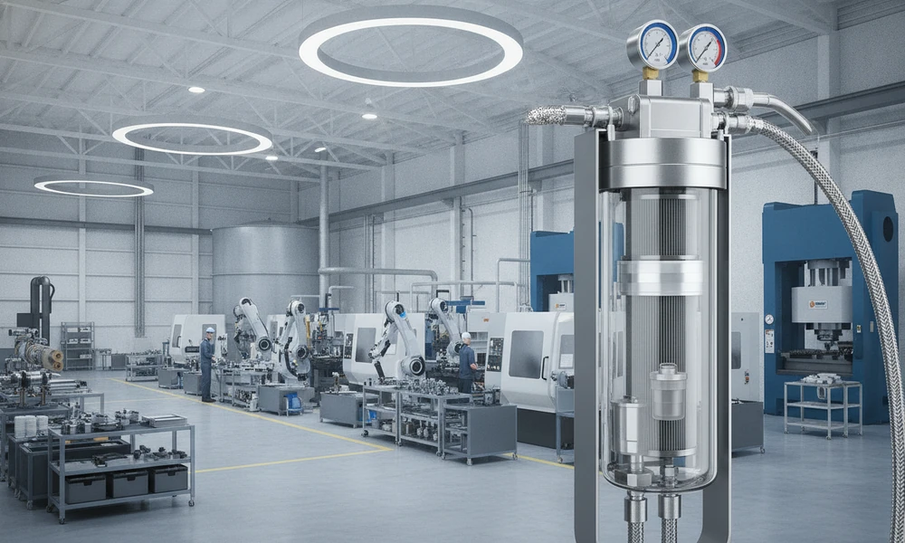
Tag – Compressed Air Filter
In U.S. industrial plants, compressed air is like a utility but also carries risks. A smart Compressed Air Filter plan protects assets, meets specs, and keeps production moving.
Clean air in the plant is practical, not perfect. It means controlling particles, water, and oil. This keeps tools, valves, instruments, and product-contact areas stable.
This guide explains industrial compressed air filtration for maintenance and engineering teams. It covers manufacturing and process industry needs, from filter choice to upkeep.
You’ll learn about common filter types and how ISO 8573-1 classes apply. You’ll also discover how to size for SCFM while keeping pressure drop low. The aim is to improve compressed air system efficiency, reduce defects, and avoid surprises during audits.
Key Takeaways
- A Compressed Air Filter strategy starts with the contaminants that matter most: particles, water, and oil.
- Industrial compressed air filtration choices should match the job, not a one-size rule.
- Manufacturing compressed air quality can affect uptime, scrap, and rework on the floor.
- Process industry compressed air often needs tighter control for odor, vapor, and product risk.
- Filter sizing must balance SCFM demand and pressure drop to protect compressed air system efficiency.
- In U.S. industrial plants, clear documentation supports audits and customer specifications.
Why Clean Compressed Air Matters in Manufacturing and Process Industries
In many U.S. plants, compressed air is more important than power or water. Dirty air can quickly cause problems in tools, valves, and controls. This can turn a smooth operation into a stop-and-go mess.
Clean air helps prevent downtime by making systems work smoothly. It also improves yield by reducing waste from air-driven tasks. The goal is to have reliable compressed air without surprises.
How contamination impacts uptime, product quality, and yield
Contaminants can make equipment behave strangely under load. This can lead to sticking valves, cylinder wear, and sensor fouling. These issues can trigger alarms, slow down cycles, or cause instrument-air failures.
Clogged nozzles and weak air knives can also cause residue. This residue can show up as product defects. Quality issues are often the first sign of a problem.
Common sources of contaminants in industrial compressed air systems
Most problems start upstream and spread downstream. Ambient intake dust, compressor wear, and oil carryover add solids and aerosols. Wet receivers, undersized or ineffective dryers, and corroded piping can add water and rust.
Drainage and maintenance habits are also key. Poor condensate drainage and open lines during repairs can let dirt in. Dirty installs can push debris into regulators, solenoids, and precision orifices.
| Contaminant | What it does in the system | Common operational result | Where it often comes from |
|---|---|---|---|
| Particles (dust, rust, pipe scale) | Abrasive wear, blocked orifices, sticky valve spools | Pneumatic tool drift, clogged nozzles, sensor fouling | Ambient intake dust, corroded piping, disturbed lines during maintenance |
| Water (liquid and condensate carryover) | Corrosion, freeze risk, damage to actuators and air pilots | Instrument-air failures, ruined coatings, unstable cycle times | Wet receivers, poor condensate drainage, undersized or ineffective dryers |
| Oil (aerosols and vapor) | Residue on parts, elastomer swelling, surface defects in finishing | Fisheyes in paint, adhesion problems, taste/odor concerns in sensitive processes | Oil carryover, compressor wear, overheated compression stages |
Hidden costs of poor air quality in plant operations
Poor air quality rarely stays in one work cell. Extra pressure drop forces higher energy use and can increase compressor run time. This raises plant maintenance costs.
Teams also lose hours to cleaning, troubleshooting, and repeated changeouts. Repairs and scrap rise when defects trace back to the air supply. Over time, compressed air reliability becomes harder to predict.
This makes downtime prevention less consistent. When air quality is not documented, audit and customer-spec risk can add friction to daily operations.
Compressed Air Filter Selection Basics for Industrial Systems
Choosing the right filter is simpler when you think about a few things. First, what kind of contaminant is in the air? How much is there? And where does it need to be caught? It’s also important to consider how long the filter will run, how much air it will handle, and the risk level at each step.
This thinking helps show the difference between central and local filtration in everyday plant operations.
Particulate, coalescing, and activated carbon filters explained
A particulate filter catches solids like rust and dust. It protects valves and tools from damage. This is especially important in older systems or after maintenance.
A coalescing filter deals with liquid aerosols. It turns oil and water mists into bigger droplets. These droplets are then drained away, keeping instruments and cylinders clean.
An activated carbon filter controls oil vapor and smells. It’s used when small amounts of oil can cause problems. But it’s not for handling large amounts of liquid.
| Filter type | Best at removing | What it does in the system | Common placement |
|---|---|---|---|
| particulate filter | Rust, scale, dust, and pipe debris | Prevents wear and blockage in air paths and small orifices | Upstream of sensitive components and as a first stage near the header |
| coalescing filter | Oil and water aerosols (mist) | Coalesces droplets and drains condensate to reduce carryover | After drying stages or before critical equipment that cannot tolerate mist |
| activated carbon filter | Oil vapor and odor compounds | Adsorbs vapor-phase hydrocarbons to “polish” air quality | Downstream of aerosol control where vapor removal is the key need |
Micron ratings, efficiency, and pressure drop fundamentals
A filter’s micron rating shows how small it can catch. Smaller ratings mean cleaner air but can also increase pressure. This makes compressors work harder.
Efficiency is just as important as size. Plants match air quality to the most sensitive use point. They check if the selection will handle peak demand. Keeping the filter clean and monitoring pressure drop helps maintain performance.
Point-of-use vs. central filtration strategies
Central filtration protects the main header and many users. It’s easy to access for changes and sits near air treatment. This is good when many tools need similar air quality.
Point-of-use filtration targets specific areas. It’s used near paint lines and sensitive equipment. Many plants use both methods. Central filtration for overall control and point-of-use for high-risk areas.
Types of Compressed Air Filters Used in U.S. Industrial Facilities
In U.S. plants, industrial filtration is often a multi-step process. A pre-filter catches large dirt particles first. Then, high-efficiency coalescing filters remove smaller aerosols. Activated carbon adsorption is added to control vapor and odors.
For areas where cleanliness is crucial, a sterile air filter is used. This is especially true near the point of use. When steam is used for cleaning, a steam-sterilizable filter is chosen.
Pre-filters for bulk particulate removal
A pre-filter is placed before coalescers and dryers. It helps block rust, pipe scale, and debris from older pipes. This also reduces the load on later stages.
In places with frequent maintenance or dusty compressor rooms, pre-filters are key. They prevent sudden spikes in particulate carryover. This keeps valves and regulators from getting clogged.
High-efficiency coalescing filters for aerosols and oil mist
High-efficiency coalescing filters are used near compressors and after dryers. They also protect critical tools or processes. These filters capture fine liquid aerosols and act as an oil mist filter.
Drainage is crucial for these filters. Automatic drains and clean condensate paths prevent re-entrainment. Without reliable draining, the coalescer can become saturated and lose efficiency.
Activated carbon filters for oil vapor and odor control
Activated carbon stages are used when oil vapor, taste, or smell is a concern. This is common in finishing lines and areas with high packaging risk. Activated carbon adsorption targets vapor-phase contaminants.
Coalescing is still necessary upstream. Liquid oil can coat the carbon and reduce its capacity. A well-drained coalescer ahead of carbon helps maintain performance.
Sterile and steam-sterilizable filters for hygienic applications
A sterile air filter is used where air contacts product or clean equipment interiors. These filters control microbial and fine particulate. They are placed at the point of use with housings designed for clean operation.
When sanitation includes steam, a steam-sterilizable filter is chosen. It can handle repeated sterilization cycles without damage. The filter must match the plant’s steam conditions and cooldown practices.
| Filter type | Typical position in the filter train | Primary removal target | Practical plant notes |
|---|---|---|---|
| pre-filter | Upstream of dryers and coalescers; at the start of a header branch | Rust, pipe scale, dust, and bulk particulate | Helps in older piping and dusty compressor areas; reduces loading on downstream elements |
| high-efficiency coalescing | Near compressor discharge/aftercooler area; after dryers; before sensitive processes | Fine aerosols and liquid carryover; oil mist filter duty | Needs dependable automatic drains to avoid re-entrainment and saturation; monitor differential pressure |
| activated carbon adsorption | Downstream of coalescing, close to the point of use when vapor control is critical | Oil vapor, odor, and trace hydrocarbons | Liquid oil upstream can ruin capacity; stable inlet conditions improve consistency |
| sterile air filter | Point of use in hygienic or product-contact areas | Microbial and fine particulate control for critical air | Uses validated performance and suitable housings; supports clean operations and audit needs |
| steam-sterilizable filter | Point of use where steam sterilization is part of sanitation | Same hygienic targets, with tolerance for steam cycles | Requires compatible materials, seals, and procedures to handle steam, condensate, and cooldown |
Understanding ISO 8573-1 Compressed Air Quality Classes

ISO 8573-1 gives U.S. plants a shared way to define air cleanliness. It uses compressed air quality classes. This helps everyone talk the same language when air touches important areas.
The standard focuses on three main areas: particles, water, and oil. Each area has a class level. This is why specs often mention particles water oil class.
Particles, water, and oil classes and what they mean in practice
Particle class deals with solid contamination like rust and dust. Strict classes mean plants use better filtration and clean piping. This helps avoid damage to tools and products.
Water class is about moisture that affects operations. Tight targets mean using dryers and drains that keep up with demand. Loose classes can lead to corrosion and other problems.
Oil class covers aerosols and vapor, including compressor carryover. Lower oil levels require high-efficiency coalescing stages. Activated carbon is used for odor and vapor limits. Testing is crucial to catch oil vapor.
Matching ISO classes to production and process requirements
Start with the risk of failure at the point of use, not at the compressor room. Different areas like instrument air and paint booths need different air quality. Many U.S. facilities set a baseline at the main header and tighten targets at critical drops.
| Use case in U.S. plants | What typically drives the ISO 8573-1 target | Primary controls used to hold the target | Where validation testing adds value |
|---|---|---|---|
| Instrument air for control valves and actuators | Reliability, low sticking, stable dew point across seasons | Dryer capacity margin, particulate and coalescing filtration, good condensate management | Dew point trending and particle checks after piping changes |
| Paint, coating, and finishing lines | Surface quality, fisheyes, and rework risk tied to oil and particles | High-efficiency coalescing, final particulate polishing, tight oil control | Oil aerosol and oil vapor sampling at the booth supply |
| Packaging areas with product-contact risk zones | Customer specs, internal hygiene rules, and contamination prevention | Point-of-use filtration near contact zones, dryer performance verification, clean piping drops | Routine parameter-by-parameter air quality reports for audits |
| General plant air for tools and blow-off | Uptime and equipment protection more than product risk | Pre-filtration, water separation, basic dryer control where needed | Spot checks after compressor maintenance or upset events |
Documenting compliance for audits and customer specifications
When a plant claims a target, the proof is usually paperwork plus repeatable measurements. Good audit documentation ties the spec to what was tested, where it was sampled, and how the system is maintained. It also helps defend decisions when a customer calls out a specific particles water oil class.
- Air quality test reports by parameter, with sampling points, date, and method noted for ISO 8573-1 alignment.
- Filter element change records, differential pressure notes, and corrective actions after contamination events.
- Dryer performance checks, including dew point history and drain function verification.
- Current line diagrams that show compressor room equipment, filter placement, and critical point-of-use drops.
- Planned validation testing intervals tied to customer specs, process risk, and change control.
Manufacturing Applications and Filtration Requirements
In manufacturing, compressed air is crucial for quality and uptime. When filters match the job, operations run smoothly and waste is low. The goal is to block particles, water, and oil from reaching the point of use.
Pneumatic tools, actuators, and valve islands
For assembly and motion control, air quality affects tool performance. Fine grit can damage cylinders, while water causes rust and sticky parts. A stable filter upstream helps, and local FRL units can fine-tune pressure and catch debris.
Contamination in valve islands can lead to slow shifts, air leaks, or stuck spools. Oil can swell elastomers and leave residue. Tight control over particles and dry air reduces seal wear and ensures consistent response.
Paint, coating, and finishing lines
Paint line air filtration affects surface finish, not just equipment. Oil aerosols can cause defects, while water can lead to blushing and poor adhesion. Many plants use high-efficiency coalescing filtration, then activated carbon polishing near the booth or gun feed.
Keeping the dew point steady is as important as removing bulk liquid. A wet header can look fine until a pressure change sends a slug downstream. Clean air supports consistent atomization and stable film build from shift to shift.
CNC machines, instrument air, and automation systems
CNC air requirements are stricter than general shop air. Proportional valves and sensitive pneumatics react to tiny pressure swings, and moisture can throw off repeatability. In some setups, air bearings and purge circuits also depend on clean, dry flow.
Instrument air is critical for control stability. When dew point and oil vapor are inconsistent, regulators drift and positioners respond slower. Filtration paired with dryer performance helps keep automation predictable during peak demand.
Packaging lines and product-contact risk areas
Packaging compressed air can reach open cartons, films, and sometimes product-contact surfaces. This raises the stakes for odor, taste, and residue transfer, especially near blow-off, vacuum generators, and form-fill-seal equipment. Point-of-use filtration near the application reduces the chance that pipe scale or oil mist reaches the line.
Documented element changes and differential pressure checks support consistent results. When maintenance is uneven, the same line can alternate between clean runs and sudden defects. A clear filtration plan helps keep packaging output steady without surprises.
| Application area | Main contamination risk | Typical filtration focus | Common symptom when filtration is weak |
|---|---|---|---|
| Pneumatic tools and actuators | Particles and liquid water | Particulate control, coalescing for aerosols, stable pressure at point of use | Reduced tool power, sticking cylinders, faster seal wear |
| Valve islands and manifolds | Fine debris, moisture, and oil carryover | High-efficiency particulate removal and dryness to protect spools and seals | Intermittent shifts, leaks, inconsistent cycle time |
| Paint and finishing | Oil aerosols, oil vapor, and water vapor | Coalescing plus carbon polishing near the booth; dew point control | Fisheyes, craters, blushing, adhesion problems |
| CNC and automation | Moisture and fine particles in control circuits | Dry, clean air with low pressure drop to protect valves and maintain repeatability | Unstable motion, drift, alarms, inconsistent part quality |
| Packaging and product-contact zones | Residue, odor, and microbial carryover from wet systems | Point-of-use filtration close to blow-off and vacuum; consistent maintenance records | Odor complaints, film defects, unexpected residue on packaging |
Process Industry Use Cases for Compressed Air Filtration
In many plants, compressed air is split into utility and instrument air. Utility air powers tools and services. Instrument air, being cleaner, protects controls.
In chemical and petrochemical plants, air must be dry and oil-free. This prevents corrosion and fouling of controls. A mix of filters and tight condensate control is used to maintain air quality.
Refineries face more challenges due to dust and temperature changes. This can clog filters and cause corrosion. Robust pre-filters and automatic drains are used to manage these risks.
In food and beverage, air quality affects taste and trust. Oil vapor and compressor carryover are major concerns. Point-of-use filters near products help control these risks.
In biotech and sterile areas, air is treated as a controlled utility. It must meet strict standards. Sterile-grade filtration and steam-sterilizable hardware are used to meet these needs.
| Use case | Primary risk | Typical filtration and dryness focus | Operational emphasis |
|---|---|---|---|
| Chemical and petrochemical control systems | Valve sticking, corrosion, actuator failure from water and oil | High-efficiency coalescing plus fine particulate control; low dew point to protect instruments | Stable pressure, tight condensate handling, instrument reliability |
| Refining and outdoor headers | Dust ingress, pipe scale, wet slugs, corrosive carryover | Rugged pre-filtration, strong drainage, and staged filtration matched to header conditions | Monitoring, element life management, protection during upsets |
| Food and beverage contact and blow-off points | Oil vapor odor, taste impact, particulate near product zones | Activated carbon where needed for oil vapor, plus point-of-use filtration near contact areas | Documentation, verification checks, consistent line practices |
| Biopharma and hygienic utilities | Microbial and particulate risk at critical points | Sterile filtration at use points; validated dryness targets and clean changeout practices | Traceable records, controlled maintenance windows, audit readiness |
Many sites run continuously, so filters are designed for easy changeouts. Predictive maintenance keeps air quality consistent. This reduces emergency work and keeps production running smoothly.
Oil, Water, and Particulate Contaminants and How to Remove Them
Compressed air can carry three types of contaminants: liquid, vapor, and solid. Each type acts differently in pipes, so fixing it requires a specific approach. A good plan includes checking the compressor, cooling, drying, filtration, and handling condensate.
Removing bulk water vs. water vapor management
Liquid water is a problem that gravity can help solve. Removing bulk water starts with aftercooling, a moisture separator, and effective drains. If drains fail, water can flood the system.
Water vapor is harder to manage because it can’t be trapped like liquid. Dryers control it by setting the water vapor dew point. This prevents water from forming as air cools in pipes. Coalescing filters also help, but dew point control is key to stopping vapor from turning into water.
Managing compressor oil carryover and oil aerosols
Oil can move through the system in different ways. Worn compressor parts, hot conditions, or the wrong lubricant can cause oil carryover. Once in the air, oil can damage equipment and finishes.
Coalescing filters target oil aerosols and liquid mist. For smells and vapor-phase hydrocarbons, activated carbon is used. But it needs protection from liquids to work well. Keeping oil and water out of carbon is crucial for clean air.
Controlling rust, pipe scale, and particulate ingress
Solid contaminants often come from inside the system. Old pipes can shed rust, tanks can release debris, and maintenance can leave grit. Dust from outside can also get in during changes.
Pre-filtration and staged control can reduce wear on tools and protect fine filters. This approach also helps stabilize equipment by preventing solids from sticking to oil and moisture.
| Contaminant state | What it looks like in a U.S. plant | Primary removal approach | What happens when it’s missed |
|---|---|---|---|
| Liquid | Water droplets, drain discharge, wet headers after cool-down | Bulk water removal using separators, effective drains, and coalescing for remaining liquid | Downstream slugs, flooded filters, corrosion in drops and hoses |
| Vapor | Dry-looking air that still forms water at machines after cooling | Dryer selection and setpoints based on the water vapor dew point | Condensation at point of use, sticking valves, inconsistent processes |
| Oil (aerosol + vapor) | Film on fittings, odor near exhaust, residue on product-contact surfaces | Coalescing for oil aerosols; activated carbon for vapor-phase oil and odor, protected upstream | Quality defects, sensor drift, carbon fouling, higher maintenance events |
| Solid | Rust scale flakes, pipe dust after repairs, receiver tank sediment | Staged particulate control with pre-filters and fine particulate elements near sensitive loads | Tool wear, clogged or damaged valves, faster filter loading and pressure loss |
Filter Placement and System Design for Maximum Efficiency
Good compressed air filter placement starts with a clear map of how air moves through the plant. In most U.S. facilities, the best flow is simple. It goes aftercooler and moisture separation first, then the receiver, then the dryer, then staged filtration, and finally point-of-use polishing where risk is highest.
A practical step-by-step layout begins right after compression. Put moisture separation and condensate drains at the aftercooler outlet to pull down bulk water early. Next, route to the receiver to smooth demand swings and give more time for water to drop out before the dryer sees it.
For dryer protection, add a pre-filter ahead of the dryer when oil or rust is possible. This lowers the liquid and aerosol load, which helps keep desiccant and refrigeration surfaces clean. After the dryer, use upstream downstream filters in stages: a coalescing filter for fine aerosols, then any specialty media only where the process truly needs it.
Distribution piping can undo good filtration if the system design traps water. Use proper slope, drip legs at low points, and well-placed condensate drains to keep liquid from riding the header during demand spikes. Avoid dead legs that sit cold and collect water, then shed it when flow changes.
Place point-of-use polishing close to the tool, valve island, or product-contact zone. That limits recontamination from hoses, quick-connects, and older drops. It also reduces the temptation to over-filter centrally, which can stack pressure drop and raise energy cost.
Service access matters in compressed air filter placement. Isolation valves support element changes without draining the whole header, and a bypass can help keep production running where quality rules allow it. Any time lines are extended or machines are added, revisit upstream downstream filters and setpoints so ISO targets and pressure stability stay intact.
| Location in the air system | Primary goal | Typical filter or hardware choice | Placement details that protect performance |
|---|---|---|---|
| Aftercooler outlet / moisture separator | Remove bulk liquid water early | Moisture separator with automatic condensate drains | Install at the first cool point so water drops out before storage and drying |
| Receiver inlet/outlet | Stabilize pressure and reduce carryover | Receiver with drain and clean outlet piping | Use short runs, correct slope, and a drain that matches load swings |
| Dryer inlet | Dryer protection from oil, rust, and liquid slugs | Pre-filter stage sized for flow and dirt load | Keep flow direction correct and leave room for service access and gauges |
| Dryer outlet | Catch fine aerosols and stabilize downstream cleanliness | Coalescing stage as part of upstream downstream filters | Place immediately after the dryer to stop re-entrained moisture and carryover |
| Near critical tools or process drops | Final cleanup at the risk point | Point-of-use polishing filter where needed | Mount close to the application to limit recontamination from hoses and fittings |
How to Size a Compressed Air Filter for Flow, Pressure, and Load
To size a compressed air filter correctly, start with how your plant really runs. Don’t just look at what the catalog says. A filter might look good on paper but can still cause flow problems during peak times.
A good sizing plan also helps protect the filter element. Real-world conditions like wet summers and hot compressor discharge can change performance quickly. Getting the basics right up front makes sizing, load assumptions, and future changes easier to manage.
Determining required flow (SCFM) and peak demand in U.S. plants
Start by making a list of every air user in your plant. This includes tools, cylinders, and packaging lines. Use nameplates for a starting point, but confirm demand with a flow meter or plant historian data.
Next, think about peak demand. Peaks often come from short, high-flow events like part ejection. If several of these events happen at once, the filter must handle the worst-case flow without becoming a bottleneck.
Accounting for pressure drop and energy consumption
Every filter adds resistance, which shows up as compressor work. The energy cost of this resistance grows over time as elements load with dirt and oil. Many plants control this by choosing a larger housing or using parallel filters.
Track differential pressure at the filter, not just header pressure. A stable header can hide a clogged element, especially when controls ramp the compressor to compensate. That is why pressure loss should be treated as an operating variable, not a one-time design number.
Considering inlet conditions: temperature, moisture, and oil load
Inlet temperature affects air density and the filter’s rated flow. Hotter air can reduce effective capacity, so check manufacturer correction factors for your actual temperature and operating pressure. In many U.S. facilities, seasonal humidity swings also change water loading, which can raise differential pressure and shorten element life.
Oil load is another major driver. Compressors in rough duty or with carryover can push more aerosol and vapor downstream, which loads coalescing media faster. If upstream separators or drains are inconsistent, the filter may see slugging that overwhelms automatic drains and increases re-entrainment.
Planning for future expansion and safety margins
Plants rarely stay static. New machines, added shifts, and aging piping can all increase flow needs. Building in expansion capacity helps avoid a rushed retrofit that forces shutdowns or temporary bypasses.
Many teams prefer modular layouts, such as duplex or parallel housings, so one side can be isolated while the other stays online. That approach supports growth while keeping pressure stable during maintenance windows.
| Sizing input | What to capture in the field | Why it changes filter selection |
|---|---|---|
| Target ISO air quality class | Required particle, water, and oil class at point of use | Sets media type and stages needed to meet spec |
| Max operating pressure | Normal header pressure and highest setpoint during peaks | Affects housing rating and correction factors for capacity |
| Normal flow and peak events | Logged SCFM trend plus overlap timing for high-flow users | Prevents undersizing that causes restriction at peak demand |
| Allowable differential pressure | Target clean ΔP and maximum ΔP before element change | Controls pressure drop energy cost over the element’s life |
| Inlet temperature and moisture | Compressor discharge and dryer outlet conditions by season | Impacts flow rating, condensation risk, and drain loading |
| Oil and particulate loading | Compressor type, carryover history, and pipe scale/rust risk | Drives element selection, expected life, and service intervals |
| Drain method and install constraints | Available drop leg, electrical/air for drains, and clearance | Reduces flooding risk and improves maintainability |
- Confirm the filter location has stable flow and easy access for differential pressure checks.
- Use correction factors when inlet temperature or pressure differs from the catalog rating.
- Choose a configuration that can grow, so added equipment does not force a redesign later.
Maintenance, Monitoring, and Replacement Best Practices
Good compressed air filter maintenance is about today’s system, not just a calendar date. Filter loading changes with dust, compressor condition, and rust scale. Monitoring helps catch problems early and avoid production slowdowns.
Differential pressure gauges and indicators for changeout timing
A differential pressure gauge shows when to change filters. Many plants use a standard for when to change, based on the system’s load. This makes filter replacement a planned action, not a guess.
Log ΔP readings at install, during normal rounds, and before changeout. A sudden jump might mean water, heavy aerosol, or debris. Keeping these records helps explain energy spikes and pressure drops.
Service intervals, element life, and contamination events
Service intervals are important but not the only guide. Element life can shorten due to drains failing, wet receivers, or oil from compressors. Rust, pipe scale, and debris can also clog media early, even if the system looks clean.
After contamination, don’t wait for the next scheduled stop. Inspect housings, check bowls and drains, and confirm air quality. If failures keep happening, consider tuning dryers, fixing aftercoolers, or cleaning piping.
| What you observe | Likely driver | What to verify on the next round | What to record for audits |
|---|---|---|---|
| ΔP rises faster than normal | Particulate surge from rust scale or maintenance debris | Upstream pre-filter condition and receiver/piping cleanliness | ΔP readings, element part numbers, and corrective actions taken |
| Element looks wet or heavy | Water slugs, drain failure, or dryer upset | Drain operation and evidence of pooling in the housing | Inspection notes, drain checks, and any air quality test results |
| Oil residue downstream | Increased compressor oil carryover or overloaded coalescing stage | Compressor separators and coalescing stage performance | Dates, ΔP trend, and any changes made to upstream equipment |
Preventing bypass, leaks, and improper installation
Bypass prevention is about the basics. Ensure the element seats fully, end caps are clean, and O-rings are good. Follow the manufacturer’s guidance on lubrication and torque.
Finish each job with leak checks around the housing, drains, and fittings. Confirm the drain cycles to prevent liquids from re-entraining. Good records should include the element part number, install date, ΔP at changeout, and any findings that explain why the system did not match normal service intervals.
Troubleshooting Common Compressed Air Filtration Problems
When air quality drops, it’s important to check each stage carefully. Start with measurable facts like flow, differential pressure, and dew point. This can prevent small issues from becoming big problems.
Diagnosing excessive pressure drop and restricted flow
Excessive pressure drop can cause weak tools and slow cylinders. It’s often due to a clogged element. But other factors like undersized housings or liquid overload can also play a role.
Begin by isolating the problem. Compare pressure differences across each filter stage. Then, check for blocked drains or liquid in the system. Also, look for extra filtration that’s not needed.
Identifying downstream oil smell, taste, or residue
Oil odor in compressed air can come from aerosol carryover or oil vapor breakthrough. Aerosols usually point to coalescing performance issues. Vapor issues often show up when activated carbon is missing or spent.
Start by separating what you see from what you smell. Visible wetting at outlets often tracks to compressor oil carryover. A persistent odor with dry piping can align with vapor load or high inlet temperature.
Addressing recurring water in lines and seasonal humidity effects
Water in air lines is not always a dryer problem. Bulk liquid can pass downstream when separators are undersized. Summer humidity spikes raise moisture load fast, exposing weak spots in condensate management.
Vapor is different. If the system never reaches its target dew point, look for airflow that exceeds dryer capacity. Watch for pooling at low points, then check drip legs and drain timing before blaming the filters.
Tracking root causes: compressor issues, dryer problems, or piping contamination
Recurring filter alarms often point to upstream equipment health, not the filter itself. Dryer failure symptoms include rising dew point and frequent drain cycling. Compressor condition matters too, including worn rings and seals, the wrong lubricant type, or intake issues that raise particle load.
Piping contamination adds its own signature: rust scale, degraded pipe coatings, or old sealants that shed into the air stream. Track what you find by date, location, and operating load, then compare trends across shifts and seasons.
| What you notice | Most likely system area | Fast verification check | What it points to |
|---|---|---|---|
| Excessive pressure drop at one filter stage | Filter housing and element | Read ΔP upstream vs. downstream of each stage under steady load | Clogged element, undersized filter, wrong grade, or media collapse from liquid overload |
| Excessive pressure drop across multiple stages | Condensate handling and upstream separation | Confirm drain operation, separator performance, and receiver carryover | Liquid loading the filters, blocked drains, or unintended series filtration |
| Oil odor in compressed air with dry lines | Carbon stage and inlet conditions | Check carbon presence, service status, and inlet temperature history | Oil vapor breakthrough, saturated carbon, or high vapor load |
| Oily residue or wet sheen at outlets | Compressor and coalescing stage | Inspect separator drains and coalescer ΔP; look for slugs after startups | Compressor oil carryover, poor separation, or liquid oil reaching downstream media |
| Water in air lines after a humidity swing | Dryer capacity and aftercooling | Compare inlet temperature, flow, and dew point to dryer rating | Dryer overloaded, aftercooler underperforming, or seasonal moisture load exceeding design |
| Particles, rust flakes, or dark debris at point of use | Distribution piping | Check dead legs, low points, and interior corrosion at drains and drop legs | Piping contamination from corrosion, scale, or disturbed deposits after maintenance |
Conclusion
Clean air is crucial in U.S. plants. It ensures reliable motion control and stable finishes. It also makes product-contact zones safer.
The right Compressed Air Filter solutions cut downtime. They prevent fouled valves, stuck cylinders, and scrap due to air-borne defects.
The key is to match filter types to the contaminant and air class needed. Create an industrial filtration strategy to protect critical equipment and sensitive processes. This makes ISO 8573-1 compliance easier during audits and reviews.
Design details are as important as filter media. Ensure each stage is sized for peak SCFM. Manage pressure drop to avoid wasting energy or starving tools and instruments.
This balance improves compressed air quality without sacrificing flow or performance.
To maintain results all year, start with an air quality check. Map each application to its real requirement. Update the filtration train where needed, then track ΔP and document service work.
With steady monitoring and routine upkeep, Compressed Air Filter solutions are practical. They reduce downtime, improve compressed air quality, and support ISO 8573-1 compliance.